The eeColor Color3 device is designed to enhance the colors in televisions that use HDMI input. The device is supposed to work well in all types of viewing environments, with various lighting situations. But what really got me interested in this device is the chip in the center, which is an Altera Cyclone 4, 30K logic element FPGA (EP4CE30F23C6N). I initially found the device in a post on reddit asking if the header on the board was a JTAG or USB header. The author posted high resolution images and a video of the case being opened. Most of the comments seemed to agree that it was a JTAG header.
The author also noted that these devices were being given out for free (with rebate) by Newegg. So I looked around to see if I could get my hands on one for a reasonable price and found the devices being sold on Amazon (search "eecolor") for about $5 to $15! A development board with one of these FPGAs typically retails for over $100. While 30K logic elements is not huge, it is definitely a good starting place for people want to begin developing on FPGAs.
Insides
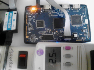
Having only worked with Xilinx products in the past, I did not have a JTAG cable for Altera products, but I found they are readily available on eBay for about $10. I plugged in the USB Blaster to the eeColor device and Quartus instantly recognized it. I was also able to upload bitstreams without trouble.
There are a few other chips of interest on the board, one of which is a 128P33BF60, which is a 16 MByte parallel flash, which is used to configure the FPGA. According to the Cyclone 4 Handbook the P33 chip is recommended in the AP configuration scheme. Also, the handbook tells us that the FPGA on board uses about 9 MBytes of this memory, so 7 MBytes should be available for other uses. I have not programmed this chip, but it should be relatively easy using the Quartus software. Another chip of note is the 48LC8M16A2, which is a 128 Mbit SDRAM. I have not confirmed that it is connected to the FPGA, but believe that it is.
The other two chips on the left and the right of the FPGA are labeled SiI9136CTU and SiI9233ACTU. These chips are HDMI transmitters and receivers, respectively. While a NDA is required to get the full data sheets of these chips, a product brief and a data brief are available for each of the chips.


The images above come from the product briefs, although there was no circuit diagram available for the SiI9233, my guess is that it does the opposite of the SiI9136. This includes HDCP Decryption. From the "AV Receiver" portion it looks like data comes in the receiver, is then decrypted and sent through the MCU (in this case the FPGA?) and then re-encrypted before transmission. I am not knowlegable about HDCP encryption, this seems like a vulnerable point for copying Hi-Def content, or modifying it.
Finally, there is an unpopulated pad above the FPGA labeled U15. I imagine that this pad probably was put there for a FTDI USB-to-Serial connection. Several of the pins connect to the FPGA. My guess is that this was used for debugging purposes, but it is odd because there is a hole in the case for a USB connection that is covered by a black sticker. I don't know why this hole would be there if USB was only designed for debugging.
Also miscellaneous components present on the board are a reg/green/orange led near the power supply. A blue led and an IR receiver in front. Also there is a push button on top. All of these elements I believe make for a good cheap starter FPGA development board.
Pinout
While it is easy to get access to the FPGA through the JTAG, the more difficult task is determining what the remaining pins on the FPGA are connected to. I noticed that as soon as I programmed the FPGA, the led near the power supply turned orange. Normally during it's intended operation it is green. I also took a multimeter to all of the unpopulated pads where the FTDI chip goes and found a voltage of around 2.7v. So I assume that the majority of the pins on the FPGA are being pulled high.

To determine which pins on the FPGA were connected to the orange led, I wrote some quick Verilog code to ground 10 pins and selected the 10 pins in the corner nearest to the led. This worked perfectly, the orange led turned off. By grounding fewer pins, I was able to determine that the red led was on pin AB19 and the green was on pin AB18. When they are both are on, it makes orange.
Using the same process and a multimeter, I was able to determine some of the pins that would go the the FTDI chip (AB14, AB15, AB16). I believe that there are 8 pins that go to open pads, I just have not checked them all yet. However to repeat my process, just watch when the pads go from 2.7v to 0v.
To find out which pins are connected to the P33 chip is a simple process, look at the pinout information provided by Altera! All of the necessary pins should be labeled under the column "Configuration Function".
Finding the clock
Finally, most FPGA designs will need a clock, so it was important to find the clock and the frequency. Between the FPGA and the JTAG is a chip labeled Y1, which is a dead giveaway that it is the clock. It is an IDT8102. By looking at the datasheet on Digikey, it looks like it could be any frequency from 4 MHz to 50 MHz, but I could not determine the frequency by it's markings.
So again, I needed to figure out which pin this was connected to on the FPGA. I narrowed the search by opening the Pin Planner in Quartus and only looking at the specific pins which are designed for a clock. I looked at row A first because it was physically closest to the chip. Then I designed a counter that would count to 50 million and change the color of the led once it reached this number, then reset. I did this because routing the clock directly to the led would make it flash to fast, but this way it would only change once a second at most. If I guessed the wrong pin, then the led (probably) wouldn't flash at all. It only took two tries and the clock was found to be at pin A12.
I found the frequency of the clock to be 25 MHz by very low tech methods. I watched the led blink with a stopwatch out and timed how long it took to blink 100 times. Using simple math, it was easy to find the frequency. While this probably is not the best method, it certainly is cheap and does not require any fancy (and expensive) equipment or a lot of coding/configuration. But looking at the data briefs of the SiI chips, this frequency makes sense. The max frequencies used in those chips is 225 MHz, or 9 times the speed of the clock.
Testing and Conclusions
Overall, I this this would make a great introductory board for anybody interested in working with FPGAs. It has a simple plug and play JTAG header, it has leds and buttons, it has an unpopulated spot where GPIO pins can be soldered. It also has access to volatile and non-volatile memory. For the more advanced programmer, maybe something interesting can be done with the HDMI connections.
I would really like to encourage people to buy these devices and share their findings. Right now they can be purchased on Amazon for less than $15, and a programming cable on eBay can be purchased for less than $10. FPGAs are an amazing technology and I would like to see a lot more people using them to create cool and innovative projects.
While my eeColor device is not being developed on I have it running as a bitcoin miner using an Open Source Bitcoin Miner. Right out the door it is capable of 15 megahashs/sec. While this is nothing compared to the ASICs that are on the market or fast GPUs, it is still comparable to CPU mining. Using the killowatt I measured it's power consumption at 2.5 watts while mining. My i7 processor also can mine bitcoins at max of around 15 megahashs/sec. I for one am impressed that this $15 piece of specialized hardware is so capable and again, I would love to see people doing some cool things with it. I will continue to work with the board and post more of my findings here.
Update 5-8-13: Many of the cheap devices on Amazon have sold out after the HAD post, try instead searching eBay for "color3 hdmi"